-
-
This step only needs to be done once. The standoffs can remain attached to the template permanently for subsequent iterations.
-
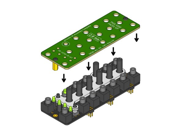
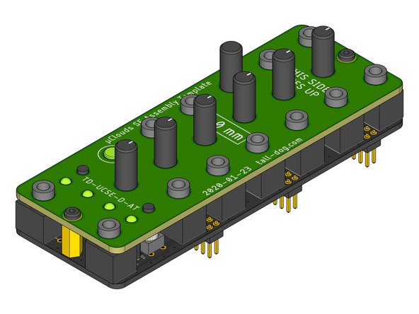
Identify the green Assembly Template. It has the part number TD-UCSE-D-AT printed on it.
-
Note the orientation of the board. The standoffs will be installed on the side that has THIS SIDE FACES DOWN printed on it.
-
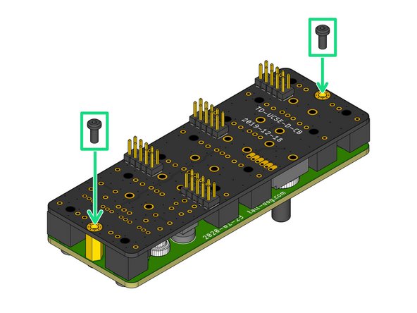
Locate two M2.5 × 10 mm female standoffs.
-
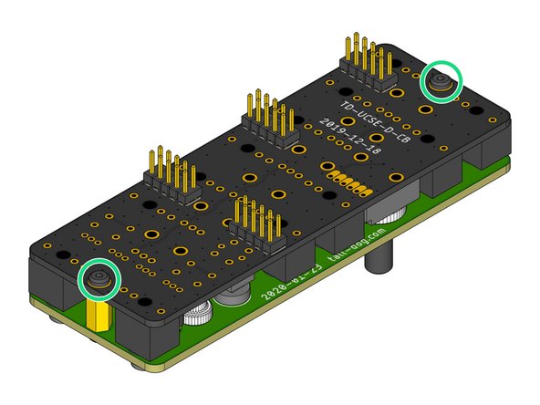
Secure each standoff using one M2.5 × 6 mm pan head machine screw in each of the two locations shown.
-
Flip over the completed Assembly Template. It is now ready to be used.
-
-
-
Identify the bare Control Board PCB. It has part number TD-UCSE-D-CB printed on its bottom side.
-
For ease of access to the solder pads, place and solder the four through-hole components H1-4 before continuing this process.
-
Do not solder any of the following components yet.
-
Place the spacer onto switch component S1.
-
Place the combined spacer and switch onto the Control Board.
-
Place the four spacer components DS1-4 onto LED components D1-4.
-
Place the four combined spacers and LEDs onto the Control Board.
-
-
-
Place all of the remaining components onto the Control Board:
-
Place the twelve jack components J1-12.
-
Place the two button components S2 and S3.
-
Place the six potentiometer components P1-2 and P4-7.
-
Place the dual-gang potentiometer component P3.
-
The leads on component P3 must be bent in order for it to fit properly next to J6. Start by using pliers to straighten all of the leads, then re-bend all of the leads down as close to the body of the component as possible. Then place the component.
-
-
-
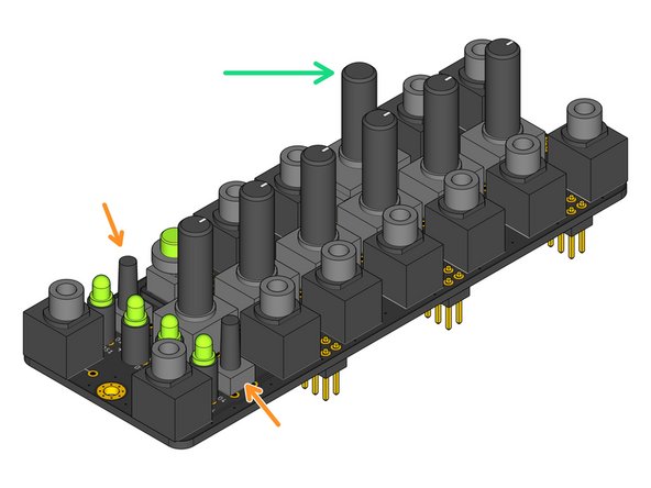
Locate the white plastic Assembly Spacer part.
-
Make sure that the flat side of the Assembly Spacer is facing up when orienting it relative to the Control Board.
-
Position the Assembly Spacer above the nine components P1-7 and S2-3 and slide it down onto them.
-
The Assembly Spacer should rest on top of the nine components with no gaps. All nine component shafts should be extending upwards through the Assembly Spacer as shown.
-
-
-
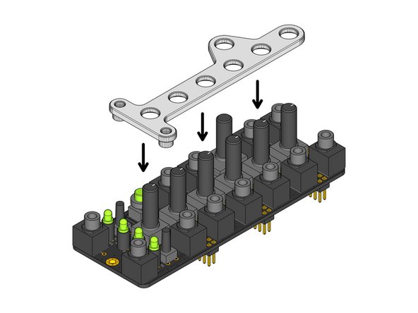
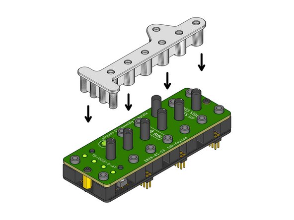
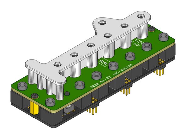
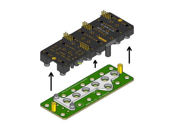
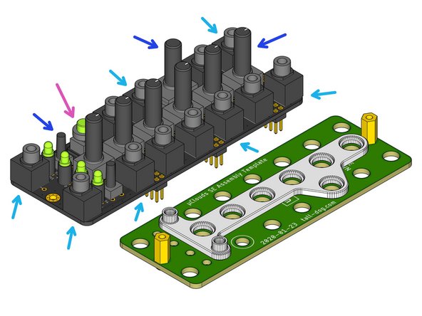
Position the prepared Assembly Template above the Control Board as shown.
-
Gently slide the Assembly Template down over all the loose components and the Assembly Spacer.
-
The Assembly Template may have to be gently wiggled in order to ensure that it is fully seated on all of the components underneath it. Both of the metal standoffs should sit flush against the top surface of the Control Board below.
-
Verify that all components are seated correctly and are sticking out through the top surface of the Assembly Template as shown.
-
-
-
Grip the pair of boards and flip them over while applying slight pressure, holding them together so that none of the components become unseated.
-
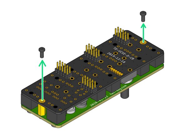
Locate and fasten two M2.5 × 6 mm pan head machine screws to secure the Assembly Template to the Control Board, sandwiching all of the loose components and the Assembly Spacer solidly in-between them.
-
-
-
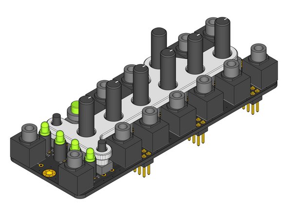
Locate the white plastic Assembly Cap part.
-
Make sure that the flat side of the Assembly Cap is facing up when orienting it relative to the top surface of the Control Board as shown.
-
Position the Assembly Cap above the eleven components P1-7 and D1-4 and slide it down onto them.
-
The Assembly Cap should rest flush up against the Assembly Template with no gaps between them.
-
Now solder all of the loose through-hole components in place. There are a total of 26 components with 92 solder joints.
-
-
-
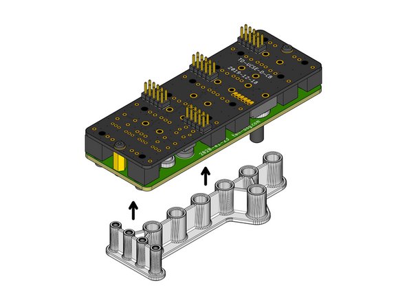
Separate the Control Board from the Assembly Cap by applying gentle pressure.
-
Put the Assembly Cap aside for use on the next iteration.
-
-
-
Remove the two M2.5 × 6 mm pan head machine screws from the Control Board side of the assembly and put them aside for the next iteration.
-
Gently lift the Control Board away from the Assembly Template and the Assembly Spacer. They should both slide off easily without applying much force.
-
Inspect the Control Board assembly and verify that all of the following statements are true:
-
There are no gaps between the plastic bases of components J1-12 and the top surface of the Control Board.
-
The shafts of components P1-7 and S2-3 rise perpendicularly (at a 90º angle) compared to the top surface of the Control Board.
-
The spacer beneath component S1 is seated flush against the top surface of the Control Board.
-
This completes the process.
-
Leave the two standoffs attached to the Assembly Template and skip Step 1 on the next iteration of this process.
-