-
-
This step only needs to be done once. The standoffs can remain attached to the template permanently for subsequent iterations.
-
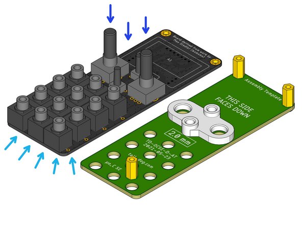
Identify the green Assembly Template. It has the part number TD-OCSE-D-AT printed on it.
-
Note the orientation of the board. The standoffs will be installed on the side that has THIS SIDE FACES DOWN printed on it.
-
Locate three M2.5 × 10 mm female standoffs.
-
Secure each standoff using one M2.5 × 6 mm pan head machine screw in each of the three locations shown.
-
Flip over the completed Assembly Template. It is now ready to be used.
-
-
-
Identify the Main Board assembly. It has part number TD-OCSE-D2-MB printed on its bottom side.
-
The Main Board should have all surface-mount soldering completed before continuing this process.
-
For ease of access to the solder pads, it is highly recommended to solder through-hole component H5 before continuing this process.
-
Do not solder any of the following components yet.
-
Place components S1 and S4.
-
Place components S2 and S3.
-
Place components J1-12.
-
Note that four pairs of these components each share a common hole for their grounding pins.
-
-
-
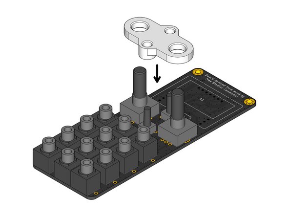
Locate the white plastic Assembly Spacer part.
-
Make sure that the flat side of the Assembly Spacer is facing up when orienting it relative to the Main Board.
-
Position the Assembly Spacer above the four components S1-4 and slide it down onto them.
-
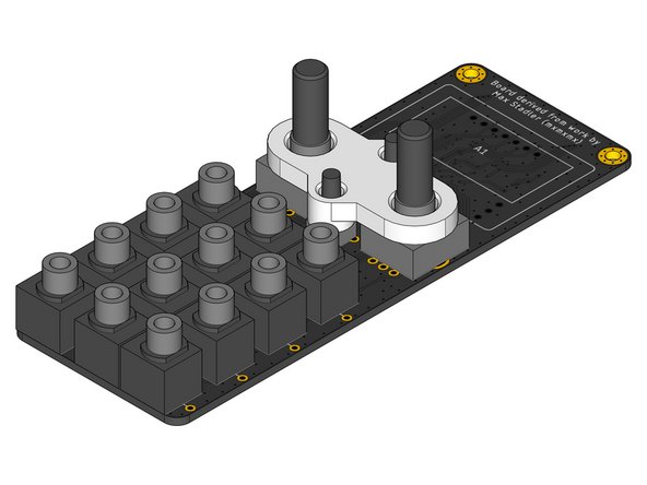
The Assembly Spacer should rest on top of the four components with no gaps. All four component shafts should be extending upwards through the Assembly Spacer as shown.
-
-
-
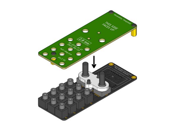
Position the prepared Assembly Template above the Main Board as shown.
-
Gently slide the Assembly Template down over all the loose components and the Assembly Spacer.
-
The Assembly Template may have to be gently wiggled in order to ensure that it is fully seated on all of the components underneath it. Each of the metal standoffs should sit flush against the top surface of the Main Board below.
-
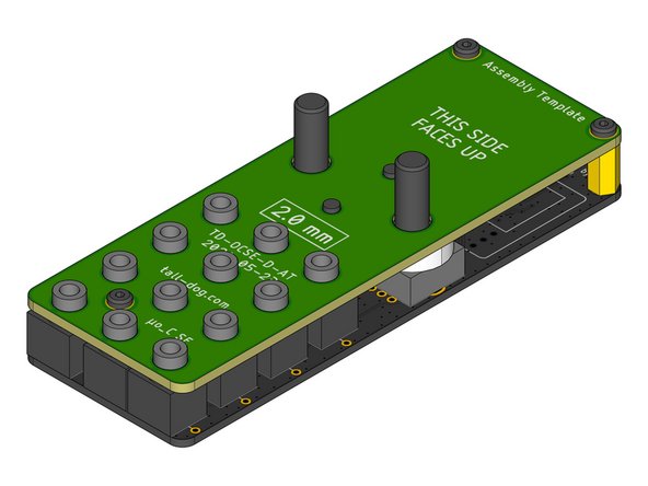
Verify that all components are seated correctly and are sticking out through the top surface of the Assembly Template as shown.
-
-
-
Grip the pair of boards and flip them over while applying slight pressure, holding them together so that none of the components become unseated.
-
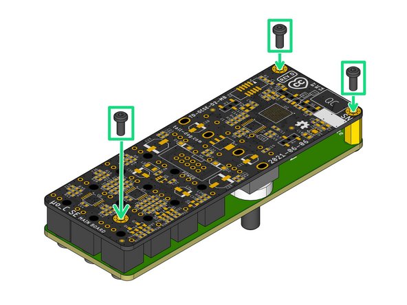
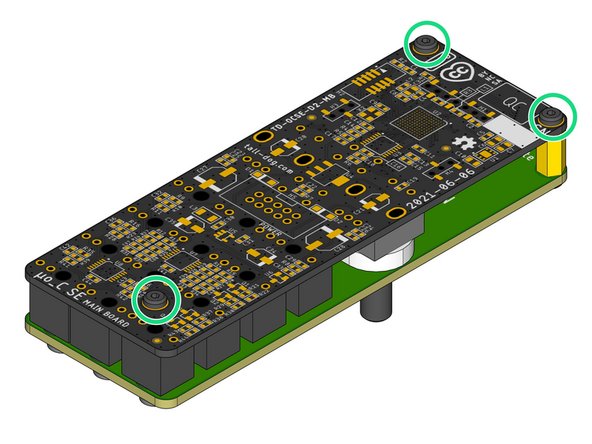
Locate and fasten three M2.5 × 6 mm pan head machine screws to secure the Assembly Template to the Main Board, sandwiching all of the loose components and the Assembly Spacer solidly in-between them.
-
Now solder all of the loose through-hole components in place. There are a total of 16 components with 58 solder joints.
-
-
-
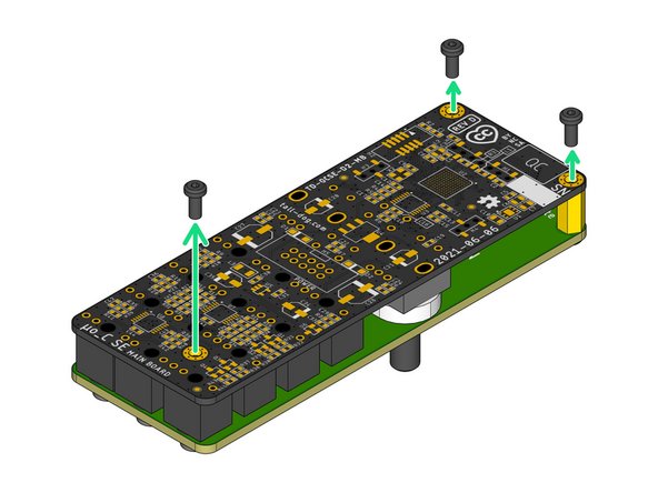
Remove the three M2.5 × 6 mm pan head machine screws from the Main Board side of the assembly and put them aside for the next iteration.
-
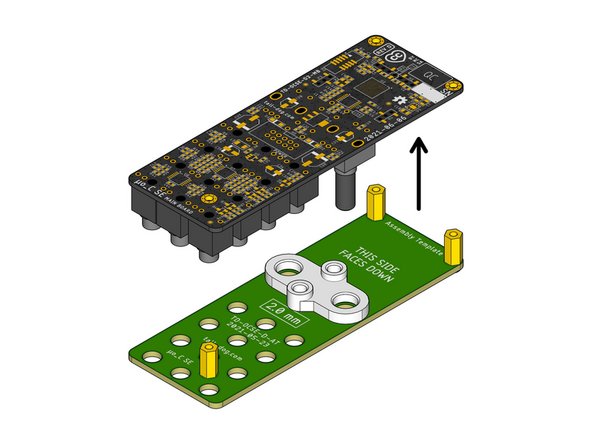
Gently lift the Main Board away from the Assembly Template and the Assembly Spacer. They should both slide off easily without applying much force.
-
Inspect the Main Board assembly and verify that both of the following statements are true:
-
There are no gaps between the plastic bases of components J1-12 and the top surface of the Main Board.
-
The shafts of components S1-4 rise perpendicularly (at a 90º angle) compared to the top surface of the Main Board.
-
This completes the process.
-
Leave the three standoffs attached to the Assembly Template and skip Step 1 on the next iteration of this process.
-