-
-
Installation of the RGB Video Kit requires that you already have a compatible RGB PPU chip. This chip does NOT come with the kit, and it must be acquired separately. Please do not begin the installation process unless you have an RGB PPU chip ready to use.
-
We very rarely have these chips available for sale, but when we do, you can purchase one of them here. They also occasionally appear on eBay or from other arcade dealers.
-
The stock aluminum heatsink typically found on these chips does not fit inside the TinyNES enclosure, and it must be removed before continuing.
-
Hot air works well, followed by the use of a razor blade to remove any remaining black thermal adhesive while it's still hot.
-
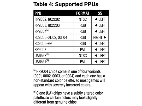
Supported RGB PPU chips include any revisions of RP2C03, RC2C03, or RC2C05.
-
Technically, RP2C04 chips can also be used, but they have non-standard color palettes, so most games will appear with severely incorrect colors.
-
RGB PPU chips were originally used in the Nintendo VS. System and PlayChoice-10 arcade machines, as well as the Famicom Titler released by Sharp in 1989.
-
RGB PPU chips are always found in white or purple ceramic DIP packages with gold plated markings and leads. Several examples are pictured here.
-
-
-
Open the kit and make sure you have all the parts:
-
Three RCA cables (one red, one blue and one green).
-
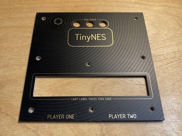
Replacement top panel with holes and markings for RGB video.
-
RGB board sealed in anti-static film.
-
RGB spacer made of white plastic.
-
1.5 mm hex driver for removing and reinstalling screws.
-
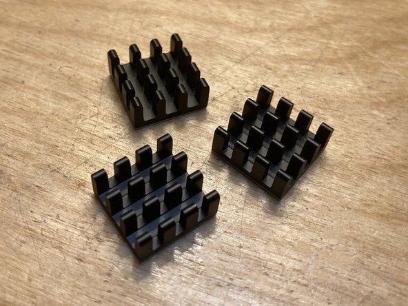
You should also have 3 small black heatsinks with thermal tape on them. These heatsinks are included with any RGB PPUs that we sell, and are also optionally included when purchasing the RGB Video Kit from us.
-
-
-
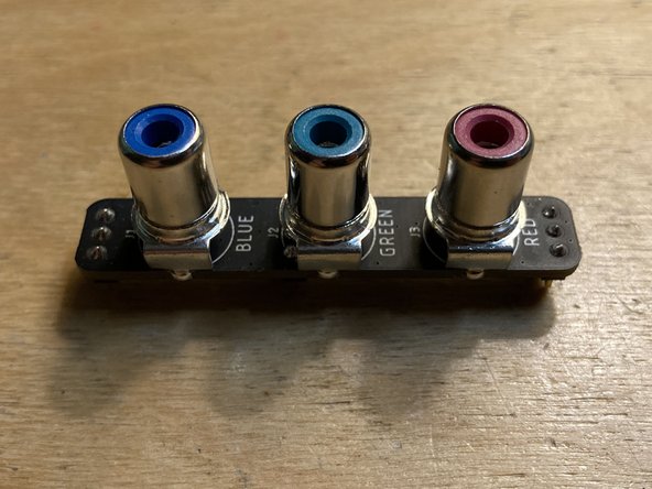
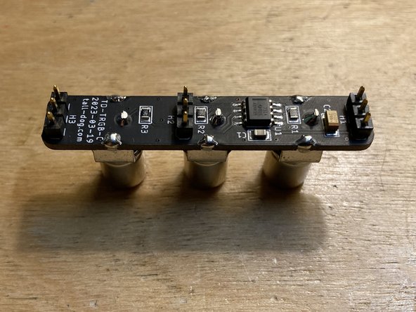
Remove the RGB board from its anti-static packaging and check it for any damage. It should be marked with part number TD-TRGB-C and have 3 sets of 1×3 pin headers installed on it.
-
Check to make sure that none of the pins on the jumper board are bent. If any of them are slightly bent, you can attempt to bend them back into position with a pair of small pliers. If any of them are damaged, please contact us for a replacement.
-
Do not touch the exposed chip on the underside of the RGB board with your fingertips. Electrostatic discharge can cause invisible damage.
-
-
-
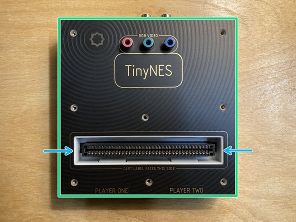
Place the TinyNES on a flat work surface. Make sure that nothing (including cables, controllers, or a cartridge) is connected to it. If the Cartridge Latch accessory is installed, please remove it.
-
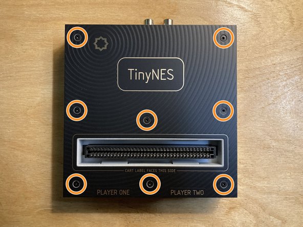
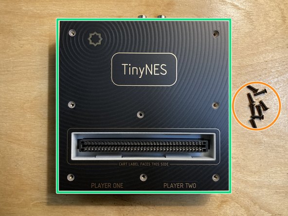
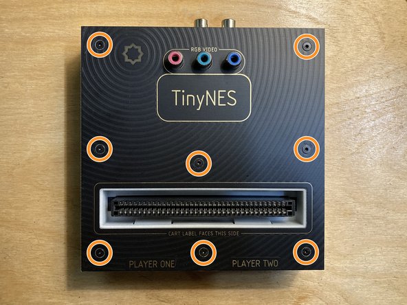
Remove the 8 marked M2.5 x 10 mm flat head machine screws from the top panel. Put the screws aside and be careful not to lose them.
-
Lift the top panel off the enclosure and put it aside.
-
Do not touch any of the exposed chips on the main board with your fingertips. Electrostatic discharge can cause invisible damage.
-
If the white plastic cartridge guide comes off with the top panel, remove it from the top panel and reposition it around the cartridge connector as shown.
-
-
-
If your TinyNES does not have a jumper board (and the associated white plastic spacer) installed, please skip directly to the next step.
-
For more information about the Jumper Board Kit, please see this guide.
-
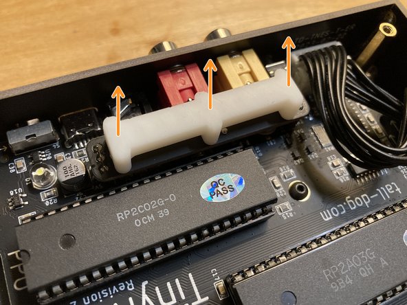
Lift off the white plastic jumper board spacer and put it aside.
-
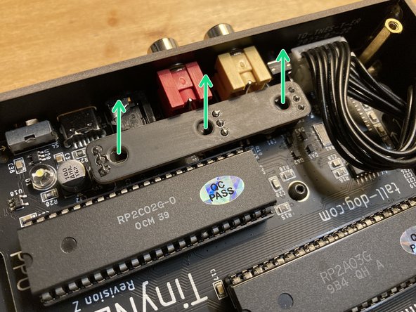
Carefully unseat and remove the jumper board from its three sockets. You may have to apply a small amount of force to remove it.
-
Your jumper board may be a different color than the black one pictured here. Some of them are green.
-
Keep the removed jumper board and spacer in a safe place, along with the original top panel, since they will all need to be reinstalled if the system is ever converted back to being in a non-RGB configuration.
-
-
-
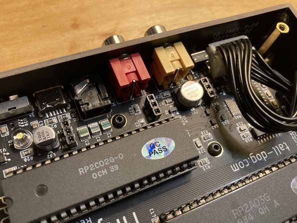
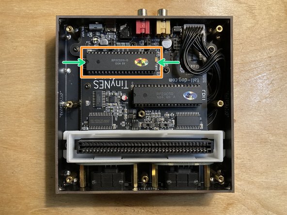
Carefully unseat and remove the existing PPU chip from its socket. You can use a chip extractor tool or a small metal screwdriver.
-
If using a screwdriver to pry the chip out, work slowly back and forth between the two short ends of the chip. Your goal is to make small gaps while preventing any of the leads from becoming bent.
-
Work slowly and brace the chip to prevent it from rotating out suddenly. If one side is raised much higher than the other, the fragile metal pins can bend or even break off.
-
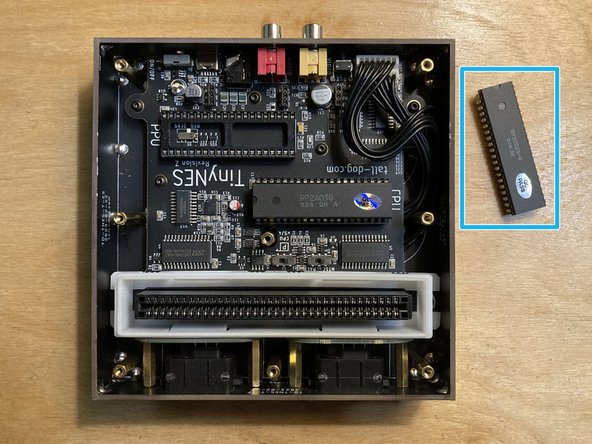
Once the chip is loose, lift it from the socket and put it aside.
-
Your new RGB chip may have come inserted into a piece of rigid foam. Push the removed PPU chip into this foam to protect its leads. Any piece of rigid foam will work.
-
Store the removed PPU carefully, ideally in an anti-static bag like the one that the RGB board came in. Tape the bag closed.
-
-
-
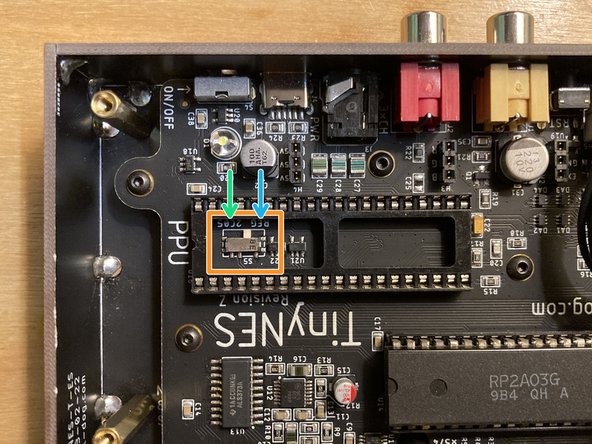
The S5 switch is located underneath the PPU chip socket and has two possible settings:
-
REG — This is how the switch should be set by default for all PPU chips except for those listed below.
-
2C05 — This position should be used only if you're installing an RC2C05-01, RC2C05-02, RC2C05-03, or RC2C05-04 chip.
-
Note that an RC2C05-99 chip should have this switch set to REG.
-
If the S5 switch is incorrectly configured, no damage will occur, but the video output from your system will be a solid color or appear scrambled, and you will have to remove the PPU in order to reconfigure it.
-
S5 switch configuration information can also be found in Table 4: Supported PPUs in the TinyNES user manual.
-
-
-
The use of a heatsink on your RGB PPU chip is strongly recommended.
-
The stock aluminum heatsink found on most RGB PPU chips is too tall to fit inside the TinyNES enclosure. We include and recommend the use of three low-profile heatsinks with machined fins. We provide them pre-fitted with thermal tape.
-
Start by cleaning the top surface of the chip with some isopropyl alcohol.
-
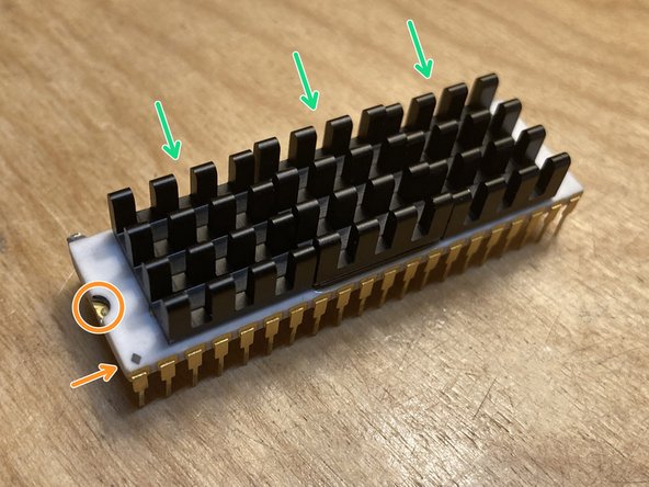
Remove the backing from the thermal tape and install the first heatsink on top of the raised area in the center of the chip.
-
Fin direction doesn't matter, but we like to install them parallel to the long side of the chip, as pictured.
-
Install the second and third heatsinks on either side of the first, as close to the center of the chip as possible.
-
Make sure that the chip's pin 1 indicators are not covered so that its orientation can be identified.
-
-
-
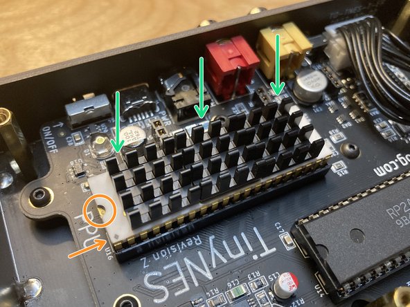
Carefully position the RGB PPU chip over the empty PPU socket.
-
Make sure that the pin 1 indicators are oriented correctly. The gold half-circle indentation and the corner mark (which is usually a gold dot, diamond, or cross) should be closest to the white lettering that says PPU on the main board, as shown.
-
Make sure that all of the pins are aligned with the metal contacts underneath them, and are not stuck on the outer edge of the socket. If not properly aligned, pins can bend or break off easily under pressure.
-
Apply even downward pressure along one of the long edges of the chip until the pins along that edge are fully seated in the socket.
-
This is somewhat counter-intuitive, since it feels like it would be easier to press down on one of the short edges first, and then the other, but doing this is actually trickier and riskier since it would angle the chip along its long dimension. The chip's pins are much happier being bent in or out than sideways.
-
Apply pressure to the opposite long edge of the chip, fully seating the chip in its socket. It should sit flat and be flush with the top edge of the socket.
-
Visually inspect all of the pins to make sure that none of them are bent or crushed.
-
If any pins are bent or crushed, you will need to carefully remove the chip and attempt to straighten or repair them. You can contact us for assistance or service.
-
-
-
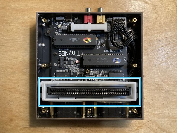
Locate the three 1×3 female sockets on the main board next to the PPU socket. They are designated H2, H3, and H4.
-
These are the same sockets that you removed the jumper board from earlier, if your system had one installed.
-
Position the RGB board over these 3 sockets. The pins on the RGB board's headers are stronger than chip leads, and are less likely to become bent or damaged.
-
The RGB board is not symmetrical and will only line up with all 3 of the sockets in one orientation, as shown.
-
Push down to seat the RGB board fully into the sockets.
-
If necessary, push aside the internal black controller port cables so they're not in the way of the RGB board.
-
-
-
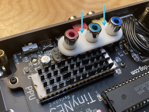
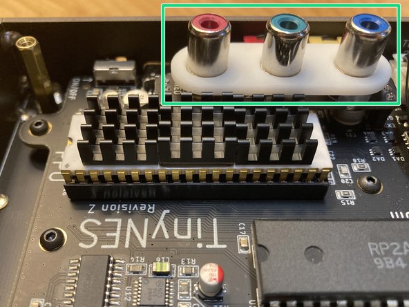
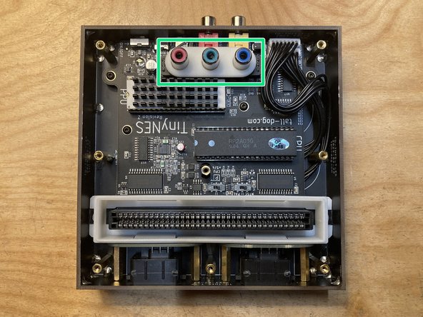
Place the white plastic spacer on top of the installed RGB board, with the RCA jacks going through the holes.
-
The spacer is symmetrical in all dimensions, so it doesn't matter which way you orient it.
-
It's okay for the spacer to be slightly loose. It will be held securely in place by the top panel.
-
Verify that the spacer and RGB board are sitting flat and that none of the black controller port wires are resting on top of them.
-
-
-
Place the replacement RGB top panel on top of the enclosure.
-
Make sure that the top edge of the cartridge guide is seated properly within the cutout in the top panel. This may or may not require a bit of force.
-
Reinstall all 8 of the screws that you removed earlier.
-
Optionally, you can also reinstall the cartridge latch at this point.
-
-
-
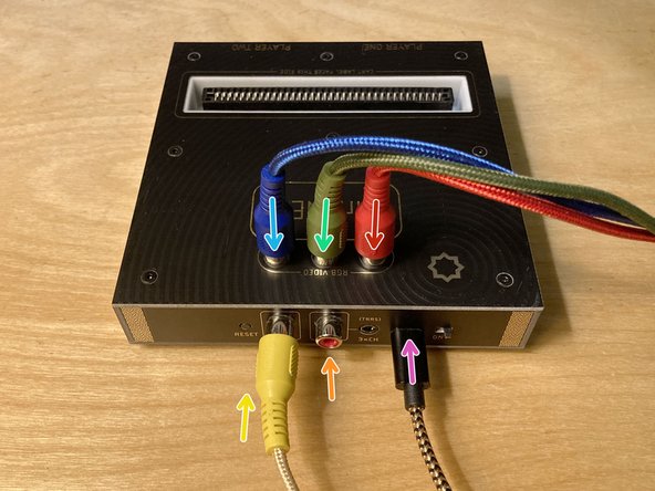
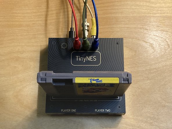
Connect the console to power and to your display:
-
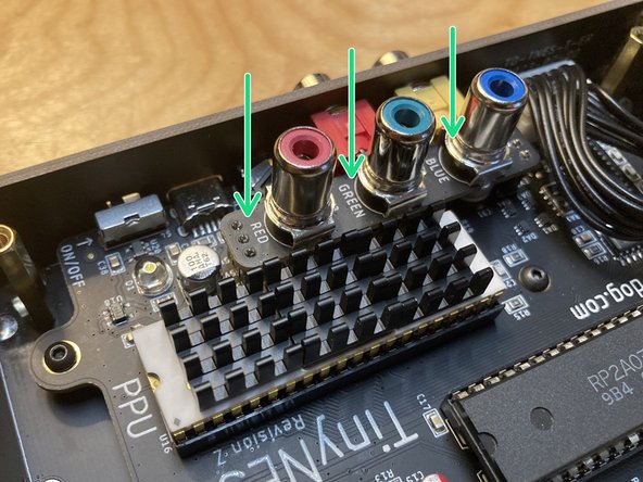
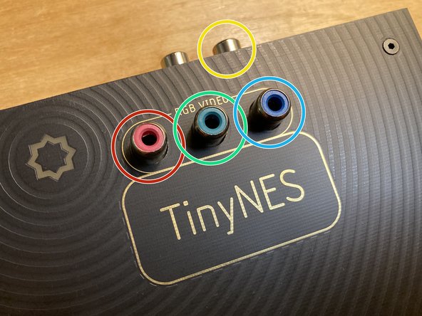
The new red RCA cable goes in the red RCA jack on the top of the console. Note that the audio RCA jack on the back of the console is also red. Try not to get the two red RCA cables mixed up.
-
The new green RCA cable goes in the green RCA jack on the top of the console.
-
The new blue RCA cable goes in the blue RCA jack on the top of the console.
-
The original yellow RCA cable goes in the yellow RCA jack on the back of the console, the same jack that formerly output the composite video signal. This cable now carries only the sync signal.
-
Audio should be hooked up the same as before using the original red RCA cable in the red RCA jack on the back of the console, or via the 3×CH 3.5 mm TRRS jack next to it.
-
Power should be connected the same as before using the original black and gold USB-C cable.
-
Connect the red, green, blue, and sync signals to your RGBS-compatible monitor or adapter. Insert a cartridge, and test to make sure that everything works correctly. You're done!
-
-
-
Your TinyNES console has now been configured to output RGBS (red, green, blue, and sync) video via 4 discrete RCA jacks. Despite the sync signal being carried separately, this is often referred to as just RGB video (the terminology around this can be very confusing).
-
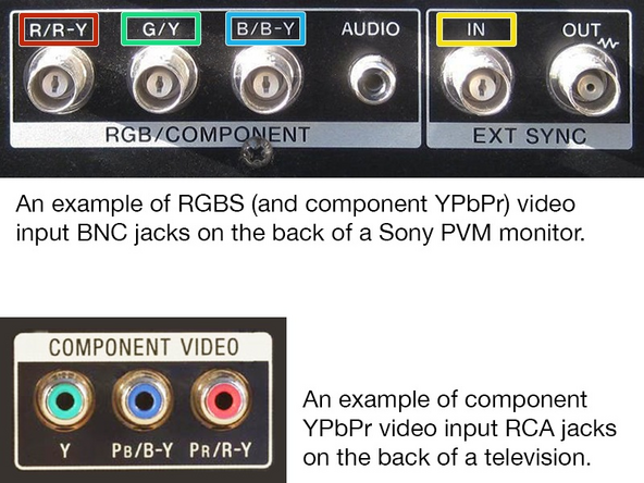
You can connect these 4 video output jacks directly to any monitor that natively supports RGBS video input, such as many Sony PVM-series monitors, among others.
-
Some of these monitors will require male RCA to female BNC adapters, like these ones available from Amazon (or many similar ones).
-
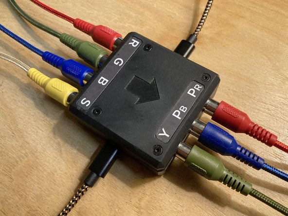
Many televisions, including modern ones, have component video input (also known as YPbPr) which is somewhat similar to RGB, but not identical. Component input usually consists of three RCA jacks which are colored green (and/or yellow), blue, and red. For this reason component video is often confused with RGB video.
-
You will need a converter to use component video. The conversion is entirely analog and does not reduce the video quality or introduce any lag. We make an RGBS-to-YPbPr converter (pictured) for this purpose.
-
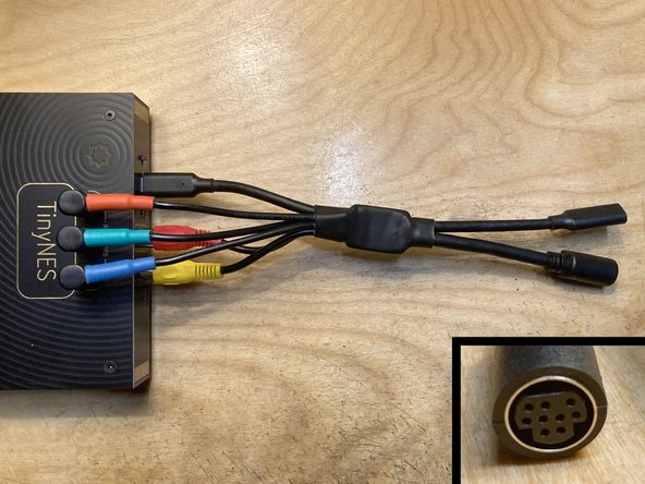
A number of video game accessories use a circular 9-pin Mini DIN connector to interface with RGB video because this particular format was used by many Sega Genesis and Mega Drive consoles.
-
You will need an adapter to use any of these accessories. We make an RGB to 9-pin Mini DIN adapter (pictured) for this purpose.
-