Tools
Parts
-
-
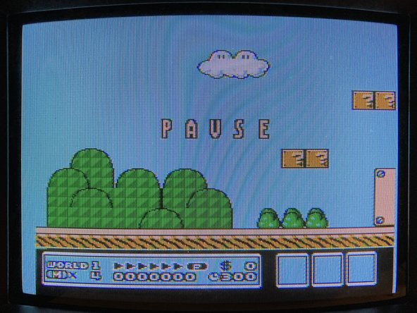
In certain cases, specific kinds of physical contact with the TinyNES enclosure may cause visual interference in the output video signal. Several examples of this interference are shown here.
-
In this example, the sky should appear as solid light blue, but instead it appears with horizontal bars of pink, orange, or black which crawl vertically, flicker, and/or may have jagged edges.
-
This issue occurs because 3 normally unused pins on the PPU chip are connected to a header for use with optional RGB output. If the header is not being used, these 3 pins are left floating, which means that they are not driven to a predictable high or a low state.
-
Despite not being utilized, the high or low state of these pins may still affect the background color palette. Tiny changes to the electromagnetic environment around these signals, such as those caused by the presence of human fingers, may translate into visible changes in the video image.
-
This issue is completely mitigated by installing the jumper board as described in this guide, which connects these three pins to ground and fully resolves the problem.
-
-
-
Make sure that you have both of the new necessary parts, and that they're both undamaged.
-
The first part is the jumper board spacer which is made of solid white plastic.
-
The second part is the assembled jumper board, which should be marked with part number TD-TDMY-A and have 3 sets of 1x3 pin headers installed on it.
-
Please note that the jumper board you receive may be either green or black, and it may have a different date on it than the one pictured here.
-
Check to make sure that none of the pins on the jumper board are bent. If any of them are slightly bent, you can attempt to bend them back into position with a pair of small pliers. If any of them are damaged, please contact us for a replacement.
-
-
-
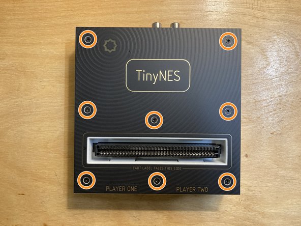
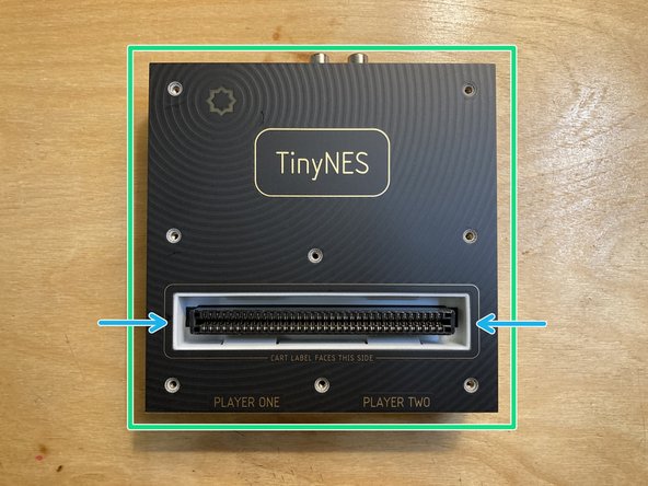
Place the TinyNES on a flat work surface. Make sure that nothing (including cables, controllers, or a cartridge) is connected to it. If the Cartridge Latch accessory is installed, please remove it first.
-
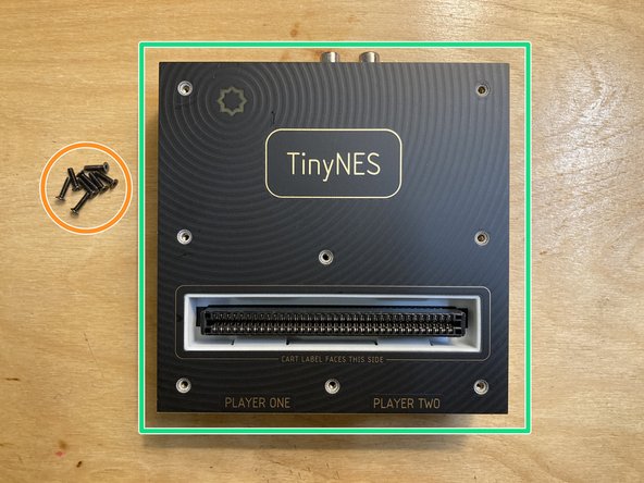
Remove the 8 marked M2.5 x 10 mm flat head machine screws from the top panel. Put the screws aside, being careful not to lose them.
-
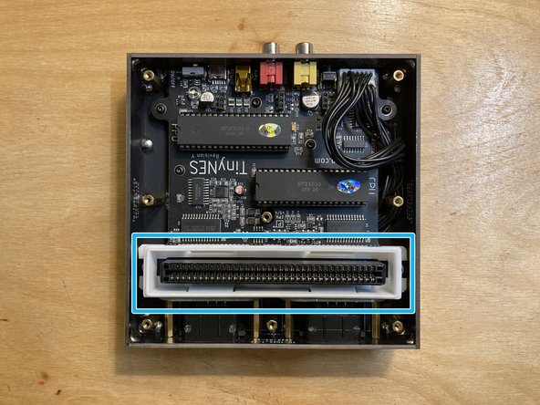
Lift the top panel off of the enclosure and put it aside.
-
Do not touch any of the exposed chips on the main board with your fingertips. Static electricity discharge can cause invisible damage to sensitive components.
-
If the white plastic cartridge guide comes off with the top panel, remove it from the top panel and reposition it around the cartridge connector as shown.
-
-
-
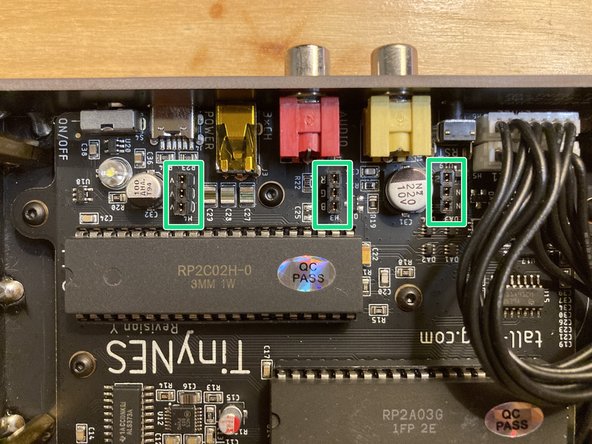
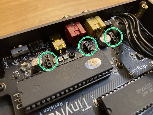
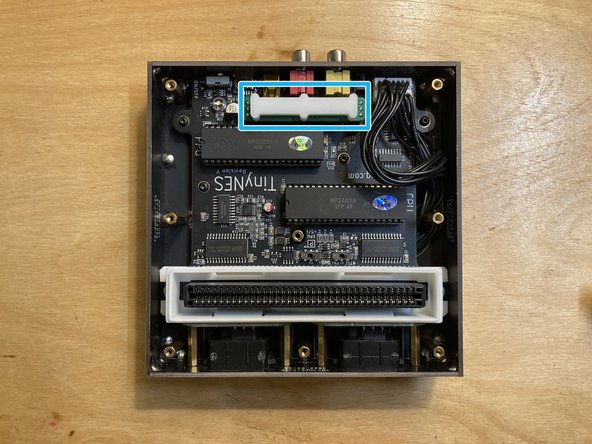
Locate the 3 marked 1x3 female sockets on the main board. These components are designated H2, H3, and H4.
-
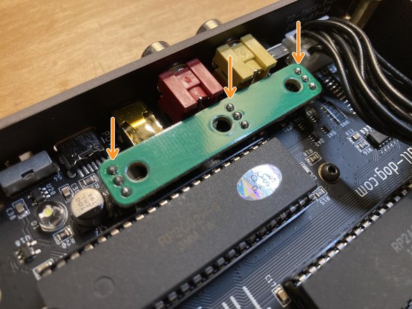
Two photos are shown here from slightly different angles in order to help you identify the locations of these 3 sockets.
-
Place the jumper board so that its pin headers align with all 3 of the sockets, then push down to seat the jumper board fully into the sockets.
-
If necessary, push aside the internal black controller port cables so they're not in the way of the jumper board.
-
The jumper board is not symmetrical and will only mate with all 3 of the sockets in one particular orientation, as shown.
-
The white printed markings on the jumper board should be facing down and should not be visible after the board has been installed.
-
-
-
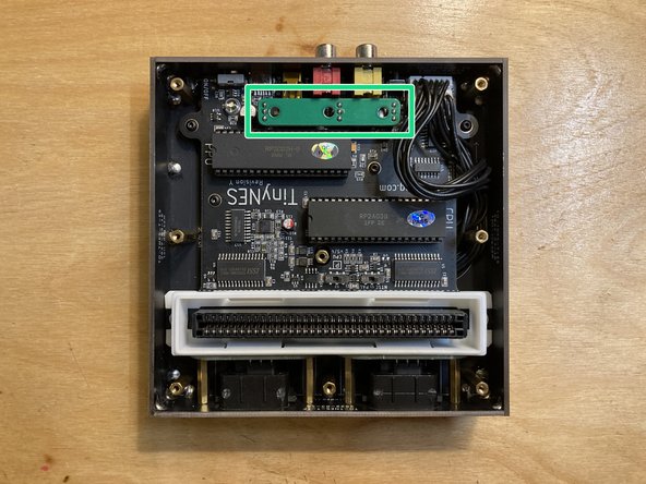
Verify that the jumper board has been installed correctly and that it's securely seated in all 3 of the sockets.
-
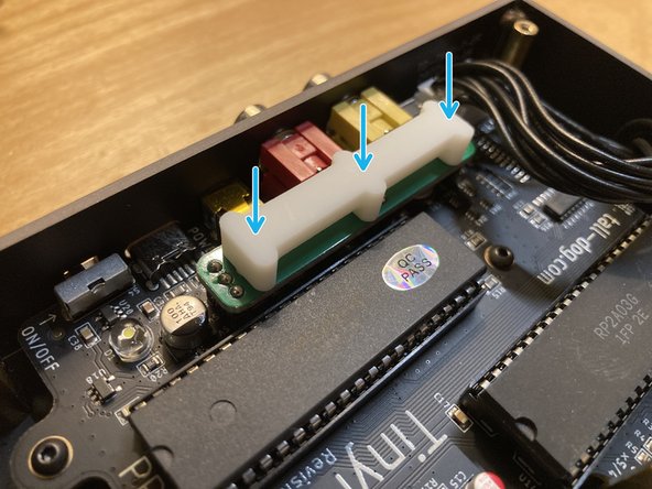
Place the white plastic spacer on top of the installed jumper board so that its 3 pegs are facing down and are lined up with the 3 holes in the jumper board.
-
The spacer is symmetrical, so it doesn't matter which way it's oriented.
-
It's okay for the spacer to be slightly loose. It will be held securely in place by the top panel.
-
-
-
Place the top panel back on top of the enclosure.
-
Make sure that the top edge of the cartridge guide is seated properly within the cutout in the top panel. This may or may not require a bit of force.
-
Reinstall all 8 of the screws that you removed earlier.
-
-
-
Connect the console back up to power and your display, insert a cartridge, and test everything to make sure that it all works correctly.
-
Any light physical contact that you make with the console's enclosure while it's running should no longer result in any visual artifacts or video interference.
-
You're done!
-
Please be aware that moving or bumping the console while it's running may momentarily break contact between any of the cartridge's pins and the console's internal cartridge connector. This may result in different kinds of graphical anomalies and/or even a system crash or reset.
-