
-
-
Want a video? Synth Seeker has created a very thorough video walkthrough which covers this guide step-by-step.
-
If you're reading this guide in a web browser, remember that you can always click on images to enlarge them.
-
Make sure you have a clean, flat work surface to perform the conversion.
-
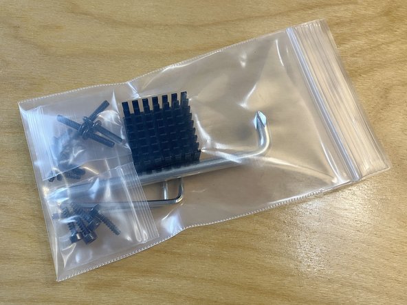
Open up the included parts bag and check to make sure that nothing is missing or damaged.
-
A list of the parts bag contents is provided here as an image. The list is also available as a PDF that you can download and print.
-
If anything is missing or damaged, please contact us right away at support@tall-dog.com so we can get you replacement parts as quickly as possible.
-
Keep the parts organized on your work surface so they don't get lost. Some of the screws and washers are small.
-
The hardware pieces are organized into little bags. Save these bags, since they will be useful for storing the screws that are left over after the conversion.
-
-
-
Shut down your Korg synth, disconnect it from power, and remove any other connected cables.
-
The photos in this guide were mostly taken with a Korg wavestate mkII but the procedure is nearly identical for the opsix, modwave, and original wavestate (non-mkII). If there are any significant differences for a particular model, they will be specifically called-out.
-
Flip the device over so the bottom surface is facing up. Be gentle in order to avoid damaging or scuffing any of the controls.
-
Place a towel or soft cloth on your work surface to provide an extra layer of protection.
-
-
-
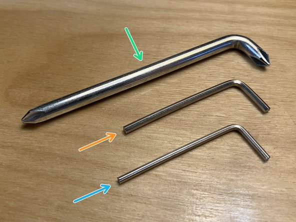
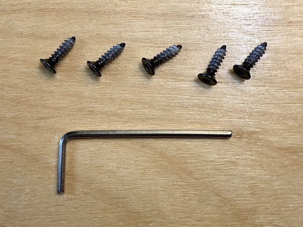
Locate the three screwdrivers from the included parts bag:
-
The #2 Phillips driver
-
The 2.5 mm hex driver
-
The 2 mm hex driver
-
The 2 and 2.5 mm hex drivers are very similar in shape and appearance, but the 2 mm one is slightly thinner.
-
-
-
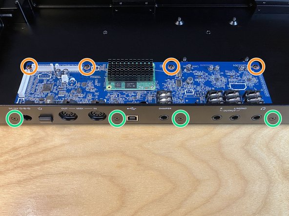
Using the #2 Phillips driver, remove the four Phillips head screws from the back panel of the device, as indicated.
-
These screws have fine threads that are designed for use with threaded holes.
-
Put the removed screws aside in a safe place.
-
Later on we will cover the suggested way to store all of the parts that are needed to reverse the conversion.
-
-
-
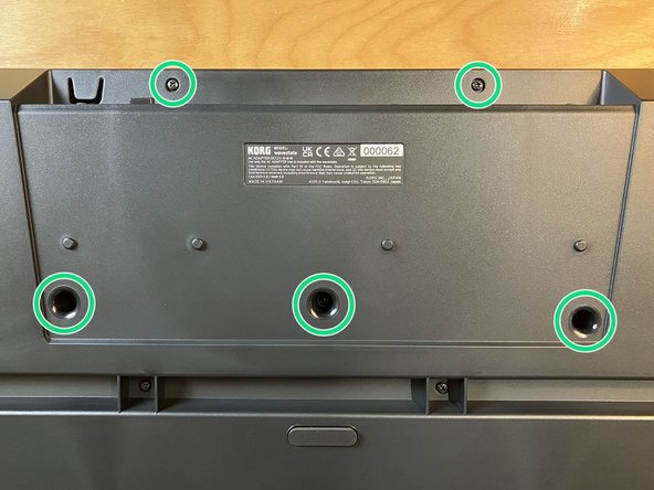
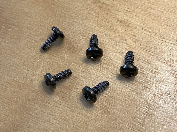
Using the #2 Phillips driver, remove the five Phillips head screws from the bottom of the device, as indicated.
-
To remove the three screws that are in wells, you may need to lift the device and tip it over. Be careful not to lose the screws as they fall out.
-
These screws have coarse threads that are designed for use with plastic.
-
There are several other Phillips head screws visible on the bottom of the device. Don't remove them.
-
Put the removed screws aside in a safe place.
-
-
-
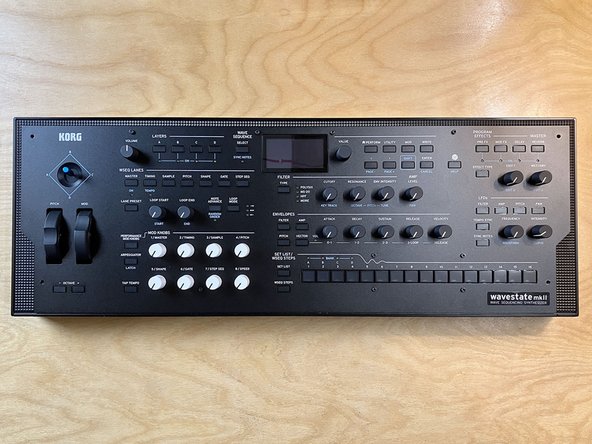
Flip the device back over so the top side is now facing up.
-
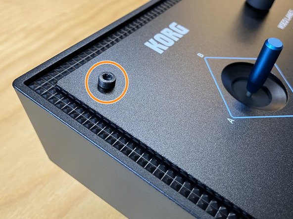
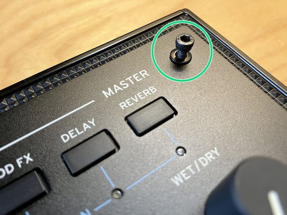
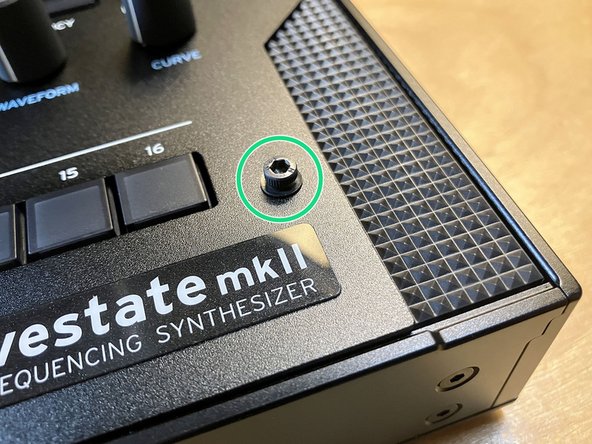
Using the 2.5 mm hex driver, remove the four socket head screws from the corners of the front panel, as indicated.
-
These screws have coarse threads that are designed for use with plastic.
-
There are several other socket head screws visible on the front panel, but all of them are smaller. Don't remove them.
-
Put the removed screws aside in a safe place.
-
-
-
Whenever possible, avoid touching any of the exposed circuit boards with your fingers.
-
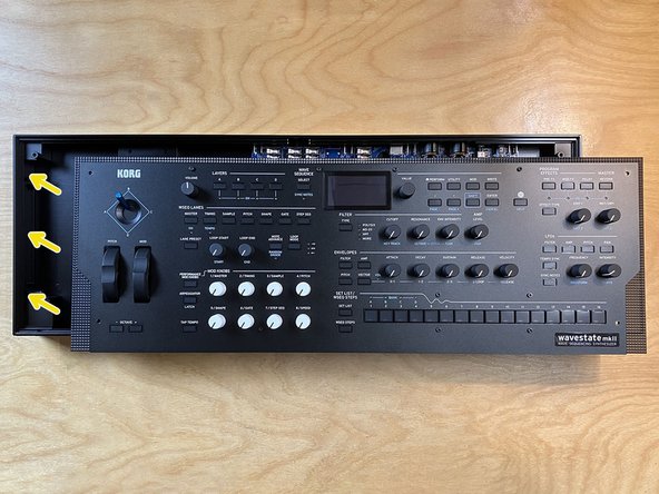
Carefully lift up the front edge of the front panel to partially reveal the internal main board and connector cables.
-
Pull up gently on several of the front panel's knobs and the mod wheels to begin lifting up the panel. If any of the knobs pop off, just push them back on.
-
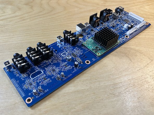
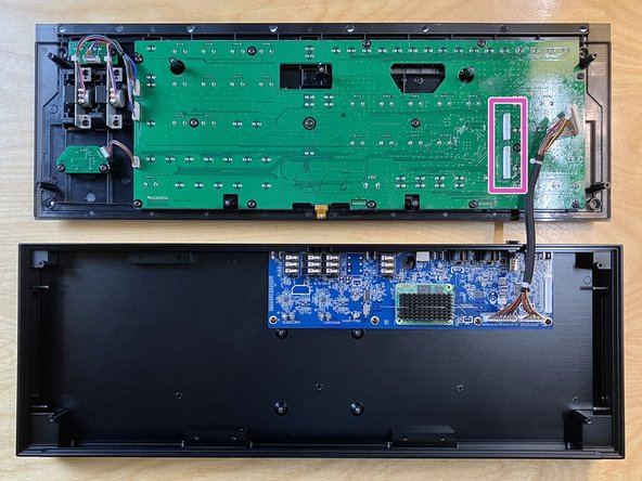
The main board on your device may be either green or blue. The blue version is pictured here, but both versions are fine.
-
Go slowly because the front panel is still connected via several cables. Only lift the front edge up as far as the cables allow it to go.
-
Continue holding the front panel at this partial angle until directed otherwise.
-
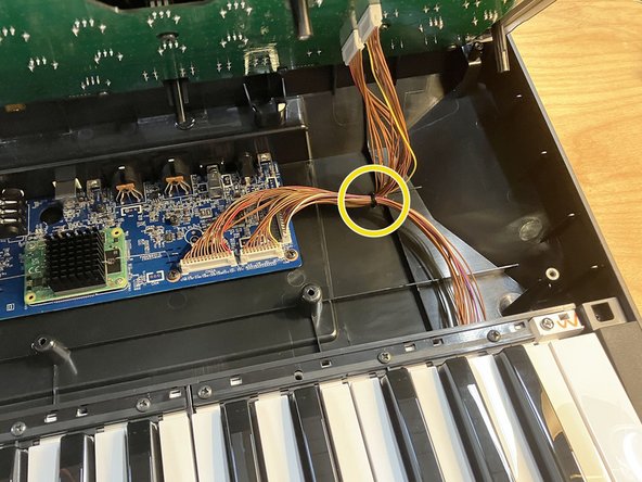
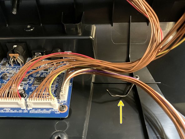
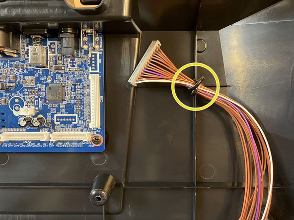
Locate the captive wire cable tie that is used to secure the connector cables.
-
Unfasten the cable tie to release the connector cables.
-
-
-
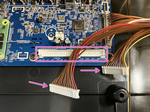
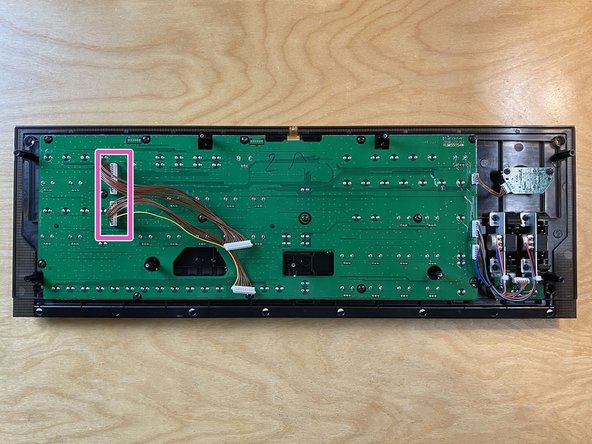
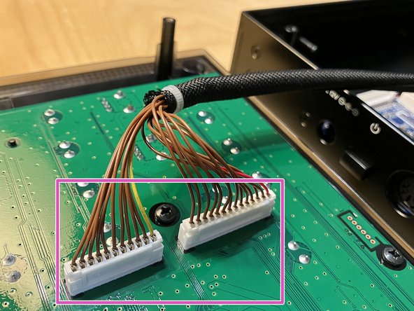
Locate the two connectors labeled CN2A (which has 14 pins) and CN3A (which has 11 pins) along the bottom edge of the main board.
-
These connectors have the same names and locations on both the blue and green versions of the main board.
-
Disconnect both of these connectors by firmly pulling each connector away from the board, one at a time. Wiggling them from side to side can help. They are held in place by friction.
-
Do not pull on any of the individual wires that make up each cable, as this risks damaging them. However, you can safely pull on all of the wires at once to loosen and free the connector.
-
Lift and remove the entire front panel away from the plastic enclosure, now that all of the cables that were holding it in place have been disconnected.
-
-
-
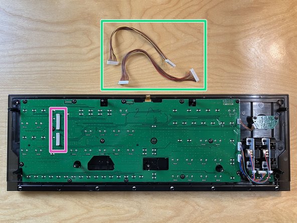
Flip over the front panel so the circuit board side is facing up.
-
Disconnect the two cables from their housings on the front panel. These connectors are the same as the ones from the previous step, and you can use the same techniques to loosen and remove them.
-
While this circuit board is less sensitive than the main board, it's still a good idea to touch it as little as possible with your fingers.
-
Put the two removed cables aside for the moment. We will return to them later.
-
Carefully put the front panel aside in a safe place.
-
-
-
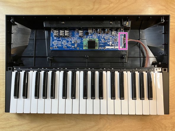
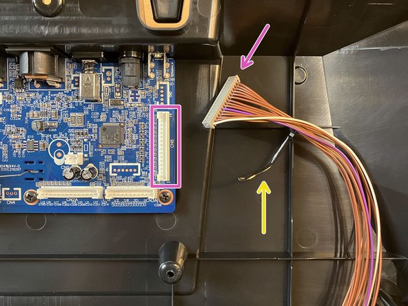
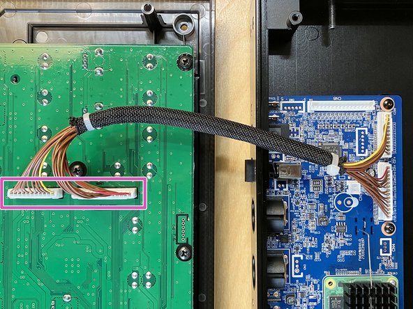
Locate the connector labeled CN8 (which has 16 pins) along the right edge of the main board. This is the keyboard connector.
-
This connector has the same name and location on both the blue and green versions of the main board.
-
Disconnect the keyboard connector from the main board, the same way that you disconnected the other two cables.
-
Re-secure the keyboard cable by wrapping the captive wire cable tie around it. This will keep it out of the way for future steps.
-
-
-
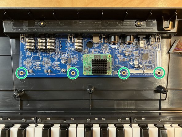
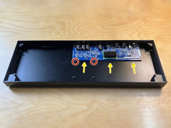
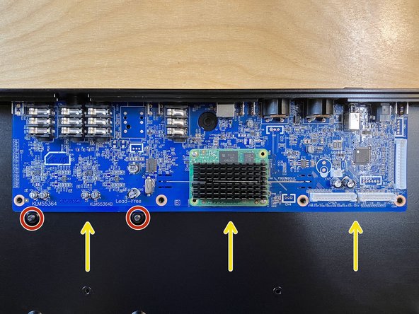
Using the #2 Phillips driver, remove the four Phillips head screws from the main board, as indicated.
-
To avoid any potential damage, don't touch any of the components on the main board with the metal screwdriver.
-
These screws have coarse threads that are designed for use with plastic.
-
These four screws are identical to the five that you removed earlier from the bottom of the enclosure.
-
Put the removed screws aside in a safe place.
-
-
-
Handle the main board with caution. Only touch it along its edges whenever possible. Do not touch any of the chips directly with your fingertips in order to avoid the possibility of damage due to electrostatic discharge.
-
Slide the main board slightly away from the rear panel, then lift it up and out of the plastic enclosure entirely.
-
Put the main board down next to the enclosure on your work surface.
-
-
-
If you are planning to transfer the serial number sticker from the original plastic enclosure to the new desktop enclosure, proceed to the next step.
-
Transferring the label is optional. Because adhesive is involved, this is the only part of the conversion process that is not necessarily perfectly reversible.
-
If you are not transferring the sticker, you are now all finished with the plastic enclosure, so you can put it aside or return it to its original packaging for storage, then skip over the next few optional steps.
-
-
-
This is an optional serial number label step.
-
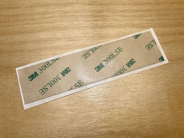
Locate the strip of double-sided 300LSE tape from the parts bag.
-
Remove the white release-paper backing from the strip of tape. You can discard the white backing paper.
-
Place the partially-exposed tape face-up on your work surface, so the remaining brown and green backing is facing down.
-
-
-
This is an optional serial number label step.
-
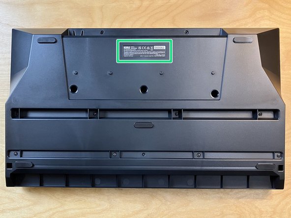
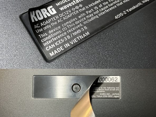
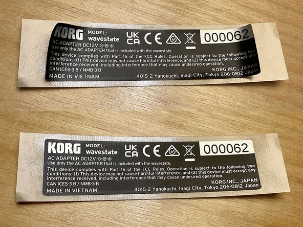
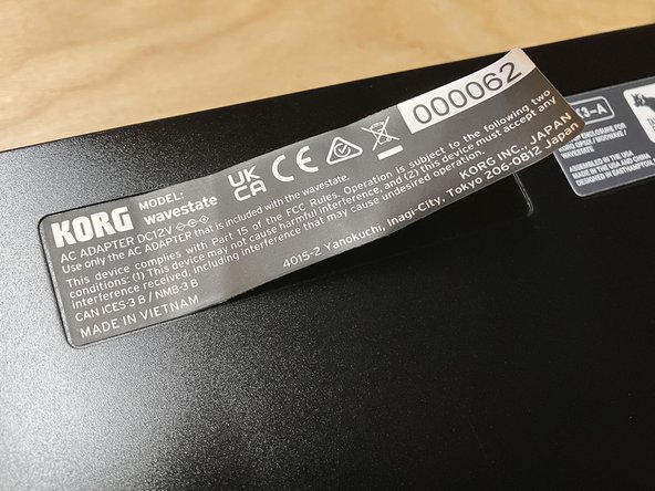
Flip over the plastic enclosure and locate the serial number label on the bottom.
-
Tip sent in by a customer: Use a hairdryer or heat gun on low to soften the adhesive, making the label easier to remove. Doing this may even make it entirely unnecessary to use the double-sided tape, so long as enough of the original adhesive remains on all edges and corners of the label after removal.
-
Do not use high heat! You could melt the plastic enclosure or damage the label. Apply heat at your own risk, and only if you know what you're doing.
-
Use a razor blade or craft knife to carefully lift up one corner of the sticker. You only need to lift up enough of the corner so you can grab the lifted portion with your fingers.
-
Grab the lifted corner with your fingers and pull the sticker directly away from the surface. If you go slowly enough, most of the adhesive should come off cleanly with the sticker.
-
Once the sticker has been removed, place it onto the exposed surface of the double-sided tape, keeping it as flat as possible. Press the surface of the sticker into the tape to eliminate any air bubbles and to make sure the bond is even and strong.
-
You are now all finished with the plastic enclosure, so you can put it aside or return it to its original packaging for storage.
-
-
-
This is an optional serial number label step.
-
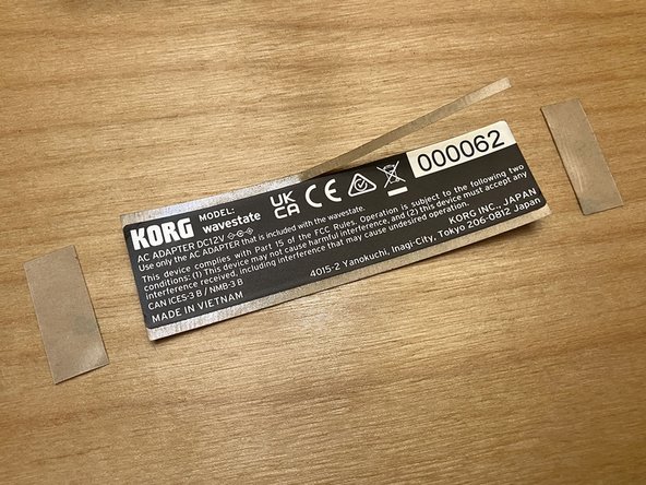
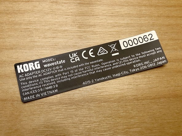
Use a pair of scissors to carefully trim the double-sided tape around the edges of the serial number sticker. Alternately, you can use a sharp craft knife and a cutting mat.
-
Start by trimming the four straight edges, ignoring the corners.
-
Since they're so small, don't worry about rounding the corners, just trim the tape diagonally on each corner.
-
The more carefully you trim the tape, the cleaner the sticker will look on the new enclosure. With some care, it's possible to achieve a nearly stock appearance.
-
-
-
This is an optional serial number label step.
-
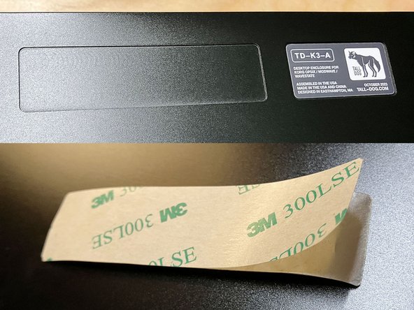
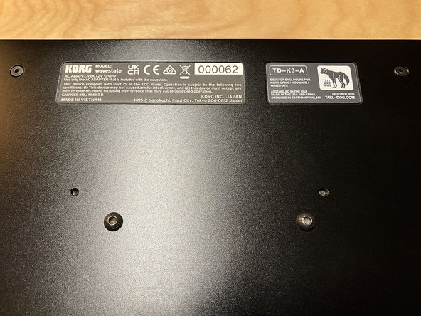
Place the aluminum desktop enclosure on your work surface, with the bottom side facing up.
-
Peel off the brown and green backing paper from the serial number label.
-
This can be tricky to get started. A razor blade, craft knife, or tweezers can help separate the backing.
-
Holding the label by its edges, position the label within the indentation on the bottom of the aluminum enclosure. Try to leave less than a 1 mm gap between the edge of the label and the indent.
-
Rub the sticker to adhere it within the indent. You can also use a lint-free cloth to press on the corners and edges.
-
Put the aluminum desktop enclosure aside for now.
-
-
-
As of this writing, Korg has released two different variants of the main board.
-
Older boards (marked KLM55055) are colored green while newer boards (marked KLM55364) are colored blue. The blue boards are slightly wider than the green ones, but the positions of all screws and jacks stay the same.
-
First-generation opsix, wavestate, and modwave units have green boards, while newer units like the wavestate mkII (and presumably also the modwave mkII) have blue boards.
-
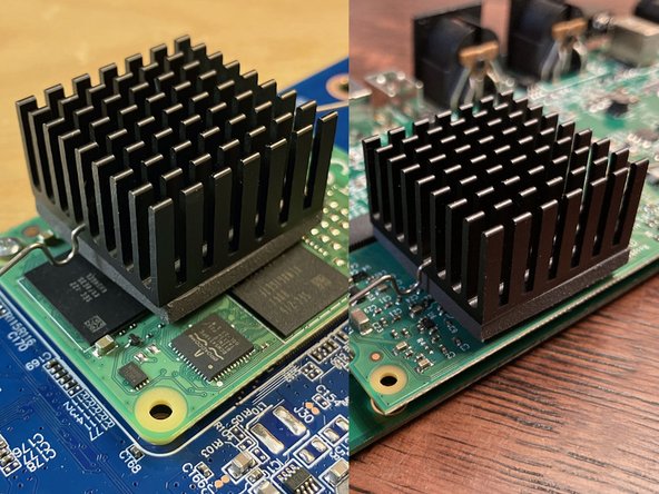
The primary functional difference between the two boards is the type of Raspberry Pi module they each use. Green boards have a Compute Module 3+ with a BCM2837B0 Cortex-A53 chip while blue boards have a Compute Module 4 with a faster BCM2711 Cortex-A72 chip.
-
The form-factor of the compute module differs between the two variants. Korg needed to design a new board revision to accommodate this change. Despite these differences, both designs use essentially the same heatsink, thermal pad, and retaining spring mechanism.
-
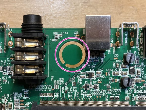
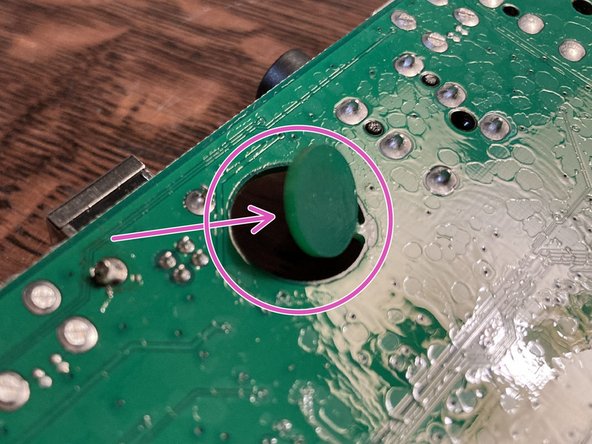
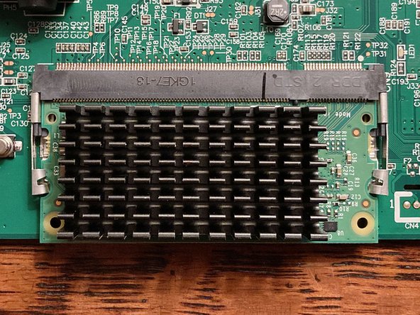
For the purposes of the next step, please note the location of the circular cutout highlighted with a magenta circle.
-
Both board variants are acceptable for this conversion and the installation procedure will be largely identical for both of them. You will see photos that show one or both board versions in future steps.
-
-
-
You may notice a wet-looking texture on the backside of the board in several of these photos. This is a flux residue from the circuit board manufacturing and cleaning process, and it is normal.
-
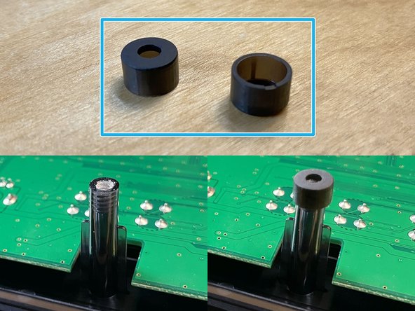
Your main board may or may not have a circular breakaway tab that needs to be removed.
-
If the tab on your board is already missing, please proceed to the next step.
-
While both blue and green main boards are manufactured with this tab, we've noticed that it tends to be present on green boards but missing on blue boards.
-
This tab serves no electrical purpose and is designed to be easily snapped off. Don't worry about damaging your board by removing it.
-
Push the tab back and forth until the central circular piece breaks off entirely, leaving only a large cutout.
-
You can discard the removed circular tab or keep it as a little souvenir.
-
-
-
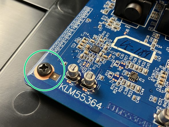
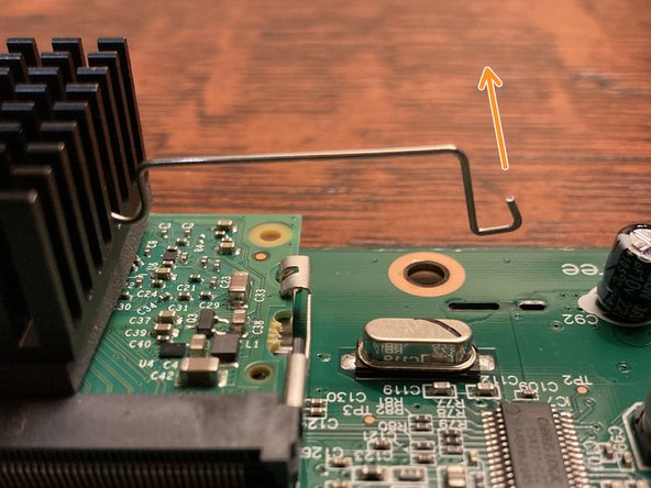
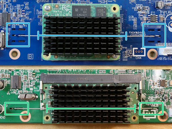
The heatsink is held in place with a bent metal spring clip that latches to the main board in two places on either side of the compute module. The green board is pictured here, but the blue board works functionally the same way.
-
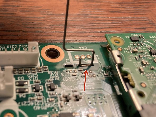
One side of the clip (highlighted here in orange) is simpler. This end is designed to be removed first.
-
The other end of the clip (highlighted here in red) has an extra bend which helps secure it. This end can only be removed after the other end has already been released.
-
Both ends of the clip are retained by a pair of slots in the main board. Each pair has an outer short slot and an inner long slot.
-
Look at the board edge-on while working with the clip so you can see how the bent ends are positioned relative to the top and bottom sides of the board.
-
Starting with the simple side (the side without the extra bend), push the clip down through the board until it releases, then allow the clip to compress so the end can be raised up through the longer slot.
-
Now that the clip can move freely, rotate it upwards by 90-degrees, so it's perpendicular to the board. Move the other end of the clip down through the board, then sideways so the end can be raised up through the longer slot.
-
Now that the clip is entirely free from the main board, put it aside somewhere safe.
-
-
-
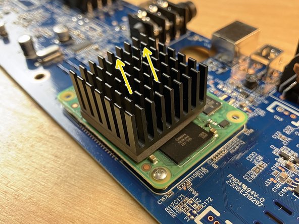
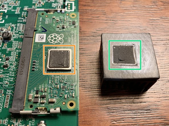
The heatsink is adhered to the chip with a gray thermal pad. This pad isn't especially sticky and it has a consistency a little bit like soft clay.
-
Pull the heatsink up and away from the chip, rotating it slightly while pulling. The heatsink should lift off pretty easily, taking the thermal pad with it.
-
Place the heatsink on your work surface with the thermal pad facing up. You should see an indentation in the pad from the outline of the chip.
-
Some gray residue from the thermal pad will probably remain visible on the surface of the chip. The amount of residue may vary.
-
-
-
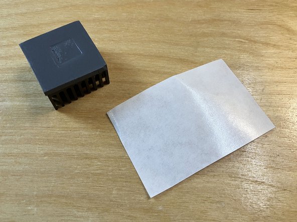
Locate the piece of white silicone-coated release paper included in the parts bag. Make sure the shiny side of the release paper is facing up.
-
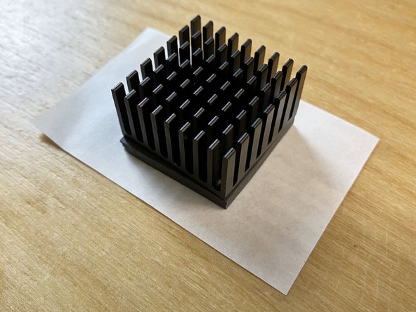
Place the heatsink down onto the center of the paper so that the gray thermal pad is touching the shiny side of the release paper. Press down lightly.
-
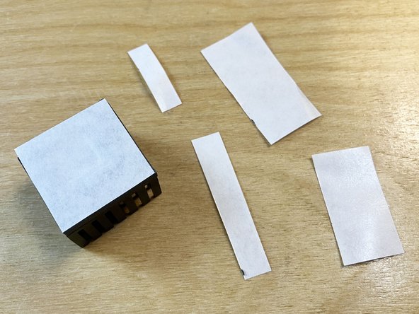
Using a pair of scissors, trim the edges of the release paper so they're flush with the thermal pad. Discard the trimmed paper scraps.
-
We preserve the original heatsink and thermal pad so the conversion can be reversed in the future. Put the original heatsink aside for now.
-
-
-
Locate the alcohol prep pad included in the parts bag. Tear open the top of the pouch and remove the small alcohol-soaked pad.
-
Use the alcohol pad to gently remove any thermal pad residue and thoroughly clean the top surface of the primary silver chip. No need to scrub, the alcohol will soften any residue.
-
The alcohol will not harm the chip or anything else on the main board. When you're done cleaning, any remaining liquid should evaporate quickly.
-
Discard the used alcohol pad and its packaging.
-
-
-
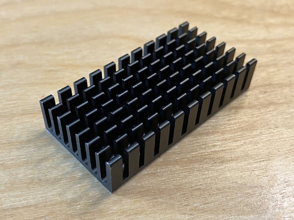
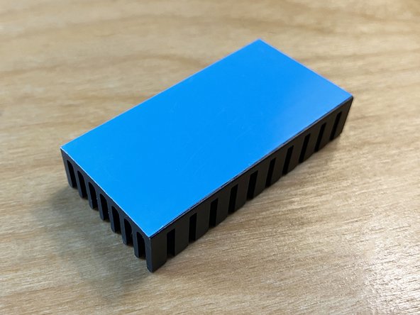
Locate the rectangular aluminum heatsink included in the parts bag.
-
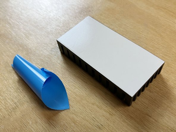
Flip the heatsink over and carefully remove the blue protective backing from the thermal pad, being careful not to touch the surface of the white adhesive with your fingers.
-
The heatsink in your kit may alternately have white protective backing instead of blue.
-
Discard the removed protective backing.
-
-
-
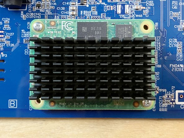
Depending on the variant of your main board, position the new heatsink above the compute module as described below. Use the photos as a reference for the proper alignment.
-
If you have a blue main board:
-
Horizontally align the heatsink so that it is centered relative to the left and right edges of the compute module board.
-
Vertically align the heatsink so that it is centered relative to the top and bottom edges of the silver chip underneath it.
-
If you have a green main board:
-
Horizontally align the heatsink so that it is centered relative to the left and right edges of the silver chip underneath it.
-
Vertically align the heatsink so that it is centered relative to the top and bottom edges of the compute module board.
-
Lower the heatsink onto the chip and then evenly apply moderate downward pressure to adhere it in place.
-
-
-
Locate the heatsink retaining clip that you previously removed. You are going to reinstall this clip in the same way that you uninstalled it, but in reverse.
-
If you have a blue main board, note that there are three different pairs of slots that the retaining clip can fit into. You should use the center pair of slots.
-
Insert the end of the clip that has the extra bend downward through one of the longer slots. Then slide it over to hook it around the little bridge between the two slots.
-
The orientation of the clip doesn't matter, so you can start on either side of the heatsink.
-
Rotate the clip down over the heatsink, placing it into one of the grooves between the fins as follows:
-
If you have a blue main board, position the spring clip into the center groove (the fourth groove from either the top or the bottom).
-
If you have a green main board, position the spring clip into the third groove from the bottom.
-
Insert the other end of the clip down through the opposite longer slot in the main board. Then pull the bent end sideways to hook it around the little bridge between the two slots.
-
-
-
Place the new aluminum desktop enclosure onto your work surface.
-
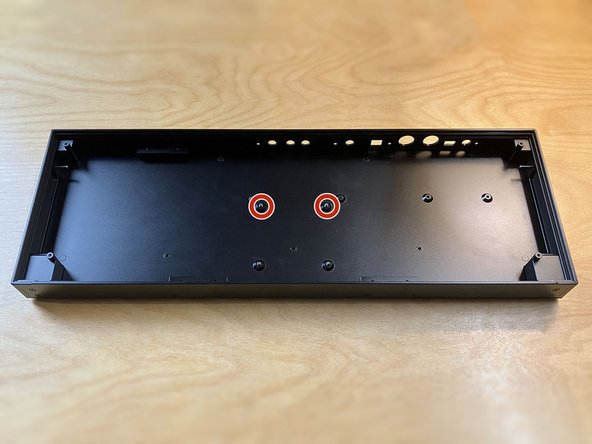
Position the main board in the enclosure so the jacks are lined up with the holes in the rear panel.
-
Be careful not to scrape the underside of the main board on the ends of either of the two nearby VESA mounting screws.
-
Carefully slide the main board back towards the rear panel so the jacks go through the holes and the board is flush with rear panel.
-
Don't force anything. The main board should fit smoothly into the enclosure without any pressure. Tip the front edge up slightly if you encounter any resistance.
-
The four mounting holes on the main board should visually line up with the screw holes underneath them.
-
-
-
Only tighten screws until they are firmly in place. Do not over-tighten them. Aggressive tightening risks stripping the screws or damaging the threads tapped into aluminum.
-
Use the 2 mm hex driver to install:
-
The four M3 × 6 mm pan head machine screws (from the parts bag) into the main board's four mounting holes, as pictured.
-
The four M3 × 8 mm flat head machine screws (also from the parts bag) into the four mounting holes on the rear panel of the enclosure, as pictured.
-
-
-
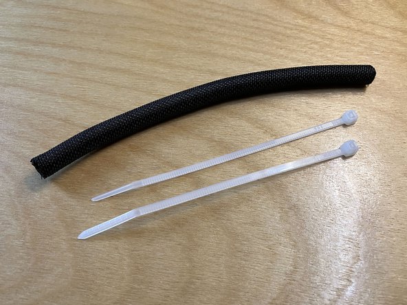
Locate the 6″ strip of cable wrap and the two 4″ cable ties from the parts bag.
-
The cable ties in your kit may be white (as pictured) or black, but there's no functional difference.
-
Locate the two cables that you disconnected earlier from the main board and front panel.
-
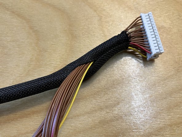
Hold the two cables together and begin wrapping both of them with the cable wrap, starting at one end and working your way along the length of the cables.
-
The cables are both the same on both ends, so their orientation to each other doesn't matter.
-
Once the cable wrap is fully around the cables, go back and smooth out any visible wrinkles or overlaps. Center the length of cable wrap relative to the two ends of the cables.
-
Install a zip tie on each end of the cable wrap, leaving about 1/4″ from each end. Pull the ties closed, then trim the excess flush with a pair of scissors or diagonal cutters.
-
-
-
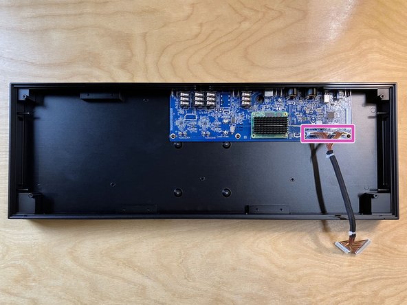
Reconnect the wrapped cables to connectors CN2A and CN3A on the main board.
-
The connectors are keyed so they can only be installed in one orientation. Make sure the connectors are oriented correctly before applying downward pressure to reseat them.
-
Since both ends of both cables are identical, it doesn't matter which end you connect to the main board.
-
-
-
Position the front panel next to the rear of the aluminum enclosure, as shown, with its circuit board facing up and its two white connectors as close to the main board as possible.
-
Reconnect the other end of the wrapped cables to the two white connectors on the front panel.
-
The connectors are keyed so they can only be installed in one orientation. Make sure the connectors are oriented correctly before applying downward pressure to reseat them.
-
-
-
IMPORTANT! Only perform this step if you're converting a wavestate (or wavestate mkII) unit. If you're converting an opsix or modwave, skip to the next step without installing these two spacers.
-
Locate the two plastic spacers from the parts bag.
-
The spacers in your kit may be a lighter gray color than the black ones pictured here.
-
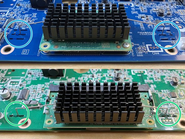
Install one spacer onto each of the two plastic bosses (pillars) that are closest to the aluminum enclosure, as indicated by the orange circles.
-
There are up to 7 additional bosses on the front panel assembly that should not have spacers installed on them. These locations are circled in red for reference.
-
Make sure that each spacer is pressed down as far as it will go onto each boss. There's no need to use very much force here. Be gentle with the plastic bosses so as not to crack them.
-
-
-
Lift and rotate the front panel to position it above the aluminum enclosure.
-
While repositioning the front panel, make sure that the wrapped cable is not caught on or blocking any of the plastic bosses as the panel is moved.
-
Align the front panel with the enclosure and lower it down. The panel should slot neatly into place. Don't worry about any small gaps at this point, but do make sure that nothing inside the enclosure is blocking the panel from being fully seated.
-
-
-
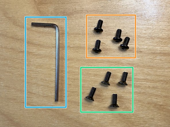
Locate the four M3 × 12 mm socket head machine screws from the parts bag.
-
Locate the four M3 washers from the parts bag. They will be located in the same small plastic bag as the socket head screws.
-
You are going to use the 2.5 mm hex key to install these screws.
-
Prepare each of the four screws by placing one washer on each.
-
-
-
Position the four sets of prepared socket head screws and washers in the four corner holes of the front panel.
-
The washers are included to prevent damage and scratches to the front panel's surface around each hole.
-
Gently thread the screws into place with your fingers, being careful not to cross-thread them or insert them at an angle.
-
Use the 2.5 mm hex key to tighten all four screws until they are firmly installed. Do not over-tighten them.
-
Some of these threaded holes were erroneously manufactured to be extremely tight, especially the holes in the two front locations (orange arrows). If this is the case for you:
-
You can try applying a very thin layer of either machine oil or liquid soap onto the outside of the screw's threads. Wipe off any excess liquid before installation.
-
If lubrication doesn't help, and if you have access to a tap wrench and an M3 × 0.5 tap, you can re-tap these two holes to resolve the issue. No cutting oil is necessary since you are just clearing out the pre-existing threads.
-
If you still have trouble with any of the screws binding or being too difficult to tighten, please get in touch with us right away at support@tall-dog.com so we can arrange a prompt resolution for you.
-
-
-
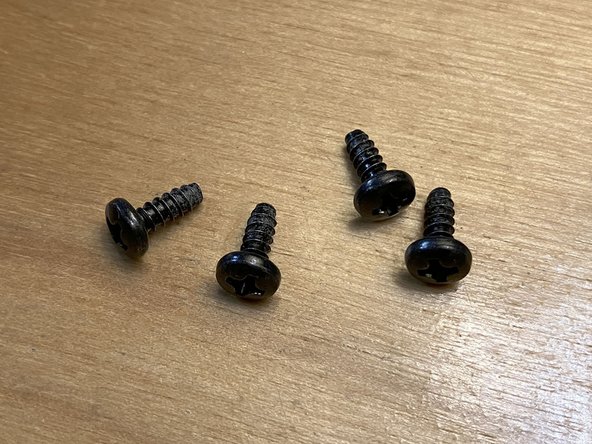
Locate the five M3 × 12 mm flat head tapping screws from the parts bag.
-
You will go back to using the 2 mm hex key to install these screws.
-
Flip the enclosure over so the bottom surface is facing up.
-
Be gentle when putting it down so you don't damage or scratch any of the front panel controls.
-
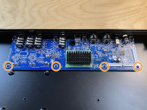
Use the 2 mm hex key to install these five screws into the five positions marked in orange.
-
You are driving these screws into plastic bosses, so go slowly and carefully. Making sure each screw goes in straight.
-
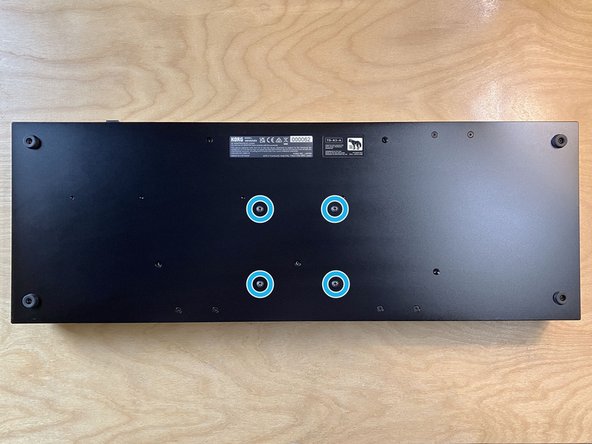
Note the four M4 pan head machine screws installed on the bottom of the enclosure. Use the 2.5 mm hex key if you need to remove these screws.
-
These screws are in a 75 × 75 mm VESA FDMI MIS-D configuration for mounting the unit onto VESA-compatible accessories.
-
-
-
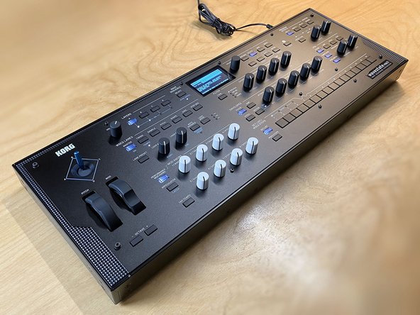
Flip the device back over so it's sitting upright again.
-
Plug in the power supply that came with the unit.
-
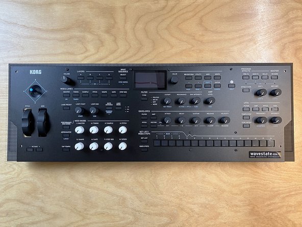
Power-on the synth and test it to make sure that everything is working properly.
-
Any issues? Check and reseat the connector cables, then retest.
-
-
-
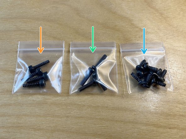
Use three of the extra small plastic zip bags to store the original hardware, which includes:
-
4 socket head screws with coarse threads
-
4 Phillips pan head screws with fine threads
-
9 Phillips pan head screws with coarse threads
-
Place these 3 little bags of screws, the original heatsink, and the 3 screwdrivers into the parts bag for safe keeping.
-
These are all of the parts and tools required to reverse the conversion. We recommend storing this parts bag with the original keyboard enclosure.
-
Congrats! This concludes the installation guide. Nice job, and we hope you enjoy using your desktop synth!
-
Confused? Did we miss something? Did you find a mistake? Or do you just think we could explain something better? Let us know at support@tall-dog.com.
-


Cancel: I did not complete this guide.
3 other people completed this guide.
Attached Documents
