Difficulty
Moderate
Steps
2
Time Required

In Progress
This guide is currently being written. Reload periodically to see the latest changes.

Private
This guide will not appear in search results and can only be viewed by team members!
Quiz
0
-
-
You only need to do this step once. The standoffs can remain attached to the template permanently.
-
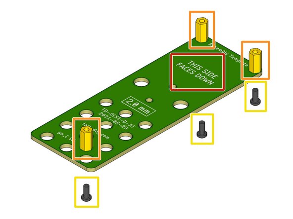
Identify the green Assembly Template PCB. It has the part number TD-OCSE-D-AR printed on it.
-
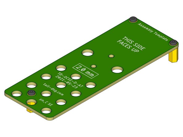
Note the orientation of the board. Standoffs will be installed on the side that says "THIS SIDE FACES DOWN."
-
Locate three M2.5 × 10 mm standoffs.
-
Secure each standoff using an M2.5 × 6 mm pan head machine screw, in the three locations shown.
-
The Assembly Template is now ready to be used.
-
-
-
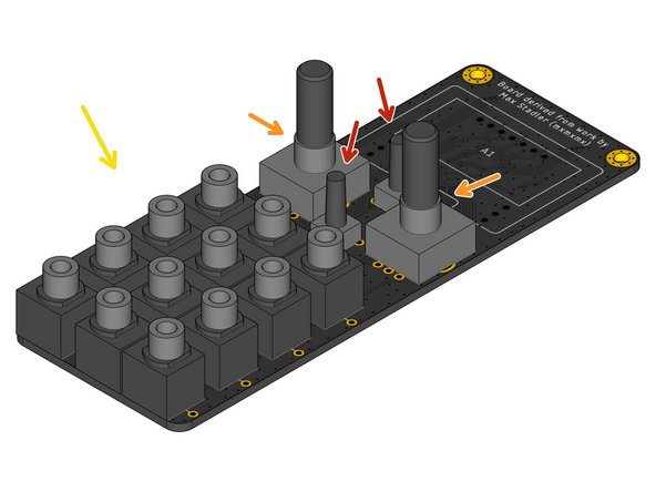
Identify the Main Board assembly PCB. It has part number TD-OCSE-D2-MB printed on its bottom side.
-
The Main Board should have all surface mount soldering already completed before continuing.
-
For ease of access to the pads, it is recommended to solder component H5 before continuing.
-
Do not solder any components until being instructed to later.
-
Populate two components S1 and S4.
-
Populate two components S2 and S3.
-
Populate twelve components J1-12.
-
Note that four pairs of these components (J1/2, J4/5, J7/8, and J10/11) share a common hole for their grounding pins.
-